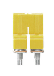
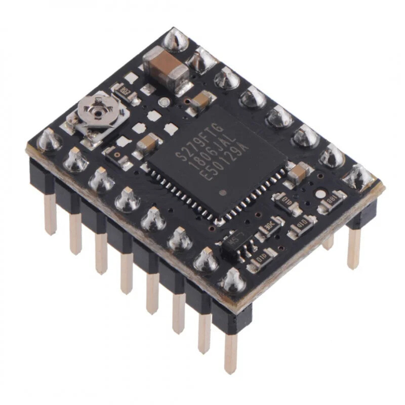
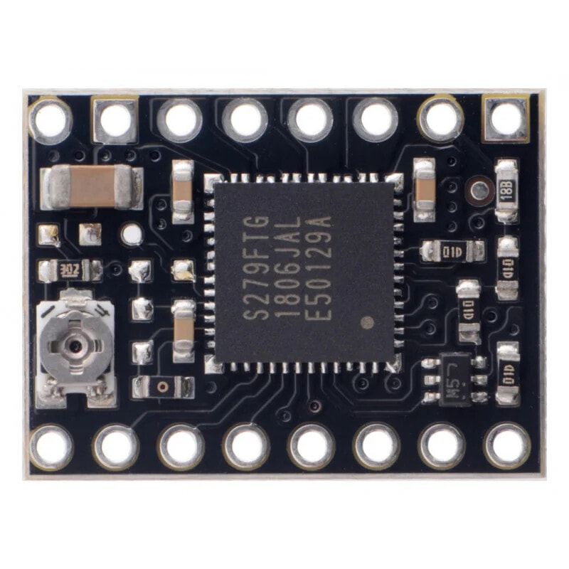
TB67S249FTG - Stepper Motor Driver 47V/1,6A with headers - Pololu 3097
- Product Code:
- 42766847


Properties
Features
- Channel
- 1
General characteristics
- Voltage To
- 10.0 V
- Voltage From
- 47.0 V
Other features
- Brand
- Pololu
Power
- Current
- 1.5 A
Description
The circuit allows to control a stepper motor with a device that allows to generate logic states e.g. Arduino.Arduino,STM32Discovoery,Raspberry Pior anymicrocontroller. Pololu module is characterized by very simple operation. Rising edge of each impulse on CLK (STEP) pin corresponds to one step. Selection of the direction is performed by giving the appropriate state to the CW/CCW (DIR) pin (e.g. low state - clockwise rotation, high state - anticlockwise rotation). The driver can also select theresolution ofmotor operation.
The module has soldered goldpin connectors.
We offer alsoversion without connectors.
TB67S249FTG - 47 V / 1,6 A stepper motor driver - with connectors - Pololu 3097.
Minimum wiring diagram to connect microcontroller to TB67S2x9FTG.
The controller requires a supply voltage from 10 V to 47 V, which will be connected to VIN and GND terminals.
To control a bipolar stepper motor, connect the circuit as shown below.
Power supplyTo supply the logic part of the module a voltage of 5 V is required.VDD PIN. Motor supply voltage from 10 V to 47 V is applied to pinVIN PIN.
Caution!
Connecting and disconnecting the motor while the controller is on can damage the system.
The step size is selected using DMODE0, DMODE1, DMODE2 inputs. The possible settings are shown in the table below. The MS1, MS2 and MS3 inputs have an internal pull-down resistor (100 kΩ).
Control.
The rising edge of each pulse on the CLK (STEP) pin corresponds to one step. Selection of the direction is done by giving the appropriate state to the CW/CCW (DIR) pin (e.g. low state - clockwise rotation, high state - anticlockwise). Ifthe motoris to rotate in one direction only, the DIR pin can be left unplugged.
When the RESET pin goes high, the driver resets its state in the translator array, which outputs to the initial value of 45°. This corresponds to 100% of the current limit on both coils in full step and non-wheel half step modes. The RESET pin does not disable the motor outputs, the controller will continue to supply current to the motor but will not give information to the CLK output
The TB67S2x9FTG can detect several error conditions that report causing one or both LO pins to be low. The manufacturer has includeda table of error combinations on the LO1 and LO2 pinsin thedocumentation.
A detailed description of each pin can be found on themanufacturer's website.
- Motor supply voltage: from 10 V to 47 V
- Current: continuous 1,6 A per coil (momentary up to 4,5 A)
- Logic part supply voltage: from 2 V to 5.5 V
- Operation in 4 different modes: full step, 1/2, 1/4, 1/8, 1/16 or 1/32
- Current limitation by potentiometer
- Protection against overheating of the circuit
- Module dimensions: 20 x 15 mm
Controller dimensions.
- Manufacturer's website: Pololu #3097
- TB67S279FTG controller documentation
- TB67S249FTG/TB67S279FTG information note
- Circuit diagram
- Motor connection manual